Printed Circuit Boards
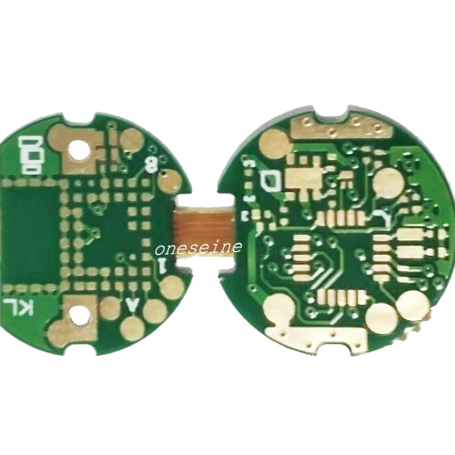
3 Layer Image Acquisition Analysis Transmission Lens Rigid Flex PCB Board
- flex circuit board
- 2 Laye6
- Polyimide Flex
- Immersion gold(ENIG)
- Product description: rigid flex pcb design guidelines flex circuit board manufacturers semi flex pcb flex circuit board fpc flexible printed circuit all flex circuits flex pcb online quote flexible rigid pcb flex
3 Layer Image Acquisition Analysis Transmission Lens Rigid Flex PCB Board
PCB Quick details:
Number of layer:6
Board thickness:Rigid part:1.2mm Flex part:0.1mm
Brand: ONESEINE
Sample order:Acceptable
Application: Electronics products
Surface finish:Immersion gold
Item:rigid-flex PCB boards.
Description:Image Acquisition Analysis Transmission Lens Three Layer Rigid Flex Circuits Board
Can you provide some examples of products that utilize rigid-flex PCB technology?
Certainly, here are some examples of products that utilize rigid-flex PCB technology:
1. Smartphones and Tablets:
- Rigid-flex PCBs are used to connect the main board to the display, camera, and other components in a compact package.
- The flexible sections allow for the components to be arranged and folded to fit the slim and curved designs of modern smartphones and tablets.
2. Wearable Devices:
- Rigid-flex PCBs are used in smartwatches, fitness trackers, and other wearable electronics to integrate the circuits and sensors while allowing the device to conform to the user's body.
- The flexible sections enable the wearable to bend and flex with the movements of the user.
3. Medical Devices:
- Rigid-flex PCBs are used in medical equipment, such as endoscopes, catheters, and prosthetic limbs, where the flexibility is crucial for navigating through the human body.
- The rigid sections provide support for the electronic components, while the flexible sections allow the device to be maneuvered and inserted into tight spaces.
4. Aerospace and Defense:
- Rigid-flex PCBs are used in avionics, satellite systems, and military equipment where weight, size, and reliability are critical factors.
- The flexible sections can help route the circuits around complex geometries and accommodate vibrations and movement.
5. Automotive Electronics:
- Rigid-flex PCBs are used in automotive infotainment systems, driver assistance technologies, and other vehicle electronics, where the flexibility allows for better integration and packaging within the limited space.
- The flexible sections can conform to the curved surfaces and tight spaces within the vehicle's interior and under the hood.
6. Industrial Machinery:
- Rigid-flex PCBs are used in industrial automation equipment, such as robotic arms and CNC machines, where the flexible sections enable the circuits to move with the mechanical components.
- This integration of rigid and flexible elements improves the overall reliability and performance of the equipment.
These are just a few examples of the diverse applications where rigid-flex PCB technology is utilized to meet the demands of modern electronic products and systems.
There are several reasons why rigid-flex PCBs are considered a more difficult technology:
You're right, rigid-flex PCBs are considered a more challenging and complex technology compared to traditional rigid PCBs. There are several reasons why rigid-flex PCBs are considered a more difficult technology:
1. Design Complexity:
- Designing a rigid-flex PCB requires careful consideration of the placement and routing of components across the rigid and flexible sections.
- Ensuring proper interconnections between the rigid and flexible layers, as well as managing the mechanical stresses, can be quite complex.
- The design process often involves advanced CAD software and specialized knowledge to optimize the layout and ensure reliability.
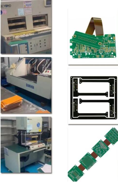
2. Manufacturing Challenges:
- Fabricating rigid-flex PCBs requires specialized manufacturing equipment and processes, which are more complex and costly compared to standard rigid PCBs.
- Ensuring proper lamination, plating, and assembly of the rigid and flexible layers can be challenging and requires tight process control.
- Defects, such as delamination or poor interconnections, can be more common in rigid-flex PCBs due to the increased complexity.
3. Testing and Reliability:
- Rigid-flex PCBs need to undergo more extensive testing to ensure reliable performance, including flexibility, bending, and environmental testing.
- Verifying the integrity of the interconnections and the overall mechanical integrity of the assembly is crucial but can be more difficult compared to rigid PCBs.
- Predicting the long-term reliability of rigid-flex PCBs under various operating conditions can be more challenging.
4. Design Constraints:
- The use of flexible materials and the need for interconnections between rigid and flexible sections can introduce design constraints, such as limitations on component placement, routing, and layer counts.
- Balancing the mechanical and electrical requirements can be a delicate process, requiring trade-offs and careful considerations.
5. Supply Chain and Availability:
- The specialized manufacturing capabilities and equipment required for rigid-flex PCBs can limit the number of suppliers and introduce supply chain challenges.
- This can result in longer lead times, higher costs, and potential availability issues compared to standard rigid PCBs.
Despite these challenges, rigid-flex PCBs have become an essential technology for many modern electronic products due to the benefits they offer in terms of size, weight, and functionality. However, it is crucial for design teams to have a deep understanding of the design, manufacturing, and testing considerations to successfully implement rigid-flex PCB technology in their products.
Frequently Asked Questions and Answers
QA 1: How long does it take to proof a single-sided flexible circuit board?
It only takes 1-3 days for flexible boards and general-purpose circuit boards. Simple single-sided and double-sided layout soft board, proofing cycle 1-3 days.
QA 2: Does ONESEINE FPC provide free circuit board samples?
Yes, if the MOQ is more than 500pcs, we can provide free samples, and at the same time will print 10pcs more for regular delivery.
QA 3: How many layers of flexible circuit boards can you sample?
There is no big difference in the production process between PCB design and proofing. ONESEINE FPC can produce circuit boards with 1-10 layers. At the same time, it has its own SMT factory to complete the process of patch assembly, and solve the customer's circuit board needs in one stop.
QA 4: How long does it take for the Flexible PCB sample of ONESEINE FPC to be finished??
In addition to the number of layers of the PCB, the wiring density, application difficulty and material grade of the circuit board will directly affect the entire cycle of circuit board proofing. We go all out and can send flex board samples within 48-72 hours.
QA 5: Is the flex circuit board proofing done by your company independently?
Yes, as the original factory in Shenzhen, China, we can complete FPC design, prototyping and mass production services in one stop.
QA 6: How to calculate the cost of flexible circuit board proofing?
The circuit board sample fee depends on the number of layers, copper thickness, size, surface treatment and other parameters.


Categories
Latest News
Contact Us
Contact: Ms Tracy
Phone: 0086 18682010757
Tel: 0086 18682010757
Add: Building9,Xinyuan Industrial Park,Tangwei,Fuyong,Baoan,Shenzhen,China
 Tracy
Tracy