Printed Circuit Boards
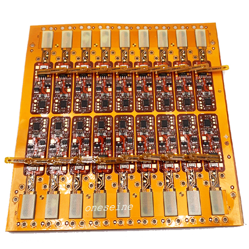
4Layer Flexible Printed Circuit Assembly For Medical Beauty Luminous Cap
- flex circuit board
- 2 Layer
- Polyimide Flex
- Immersion gold(ENIG)
- Product description: rigid flex pcb design guidelines flex circuit board manufacturers semi flex pcb flex circuit board fpc flexible printed circuit all flex circuits flex pcb online quote flexible rigid pcb flex
4Layer Flexible Printed Circuit Assembly For Medical Beauty Luminous Cap
Product Introduction
Number of layers: 2
Plate thickness: 0.13mm
Minimum aperture: 0.2
Minimum line width/line spacing: 0.1mm
Copper thickness: 1OZ
Solder resistance: yellow film with white letters
Surface technology: ENIG
Specification:The medical beauty luminous cap adopts a fixed crystal process to attach MiniLED wafers to the high-temperature white oil backlight circuit board of the PCBA module. MiniLED backlight technology can achieve local dimming and zone control, with five major advantages: brightness breakthrough, high contrast, energy saving and low power consumption, green longevity, and eye health. Shijia PCB can provide ODM services for MiniLED backlight flexible PCB components that meet the structural and functional requirements of medical and beauty hair caps.
Frequently Asked Questions and Answers
QA 1: How long does it take to proof a single-sided flexible circuit board?
It only takes 1-3 days for flexible boards and general-purpose circuit boards. Simple single-sided and double-sided layout soft board, proofing cycle 1-3 days.
QA 2: Does ONESEINE FPC provide free circuit board samples?
Yes, if the MOQ is more than 500pcs, we can provide free samples, and at the same time will print 10pcs more for regular delivery.
QA 3: How many layers of flexible circuit boards can you sample?
There is no big difference in the production process between PCB design and proofing. ONESEINE FPC can produce circuit boards with 1-10 layers. At the same time, it has its own SMT factory to complete the process of patch assembly, and solve the customer's circuit board needs in one stop.
QA 4: How long does it take for the Flexible PCB sample of ONESEINE FPC to be finished??
In addition to the number of layers of the PCB, the wiring density, application difficulty and material grade of the circuit board will directly affect the entire cycle of circuit board proofing. We go all out and can send flex board samples within 48-72 hours.
QA 5: Is the flex circuit board proofing done by your company independently?
Yes, as the original factory in Shenzhen, China, we can complete FPC design, prototyping and mass production services in one stop.
QA 6: How to calculate the cost of flexible circuit board proofing?
The circuit board sample fee depends on the number of layers, copper thickness, size, surface treatment and other parameters.
Flexible PCB concept:
Flexible printed circuit board , also known as "FPC soft board" is made of flexible insulating substrate printed circuit, with a lot of advantage that rigid printed circuit board does not have .
For example, it can be free to bend, winding, folding, can be arranged in accordance with the requirements of any spatial arrangement, and in any three-dimensional space to move and stretch, so as to achieve the integration of component assembly and wire connections. The use of FPC can greatly reduce the volume of electronic products, and suit for high-density, small, highly reliable needs. Therefore, FPC in the aerospace, military, mobile communications, notebook computers, computer peripherals, PDA, digital cameras and other fields or products have been widely used.
Flexible electronics, also known as flex circuits, is a technology for assembling electronic circuits by mounting electronic devices on flexible plastic substrates, such as polyimide, PEEK or transparent conductive polyester film. Additionally, flex circuits can be screen printed silver circuits on polyester. Flexible electronic assemblies may be manufactured using identical components used for rigid printed circuit boards, allowing the board to conform to a desired shape, or to flex during its use. An alternative approach to flexible electronics suggests various etching techniques to thin down the traditional silicon substrate to few tens of micrometers to gain reasonable flexibility (~ 5 mm bending radius)
Advantage of FPCs
Potential to replace multiple rigid boards and/or connectors
Single-Sided circuits are ideal for dynamic or high-flex applications
Stacked FPCs in various configurations
Disadvantages of FPCs
Cost increase over rigid PCBs
Increased risk of damage during handling or use
More difficult assembly process
Repair and rework is difficult or impossible
Generally worse panel utilization resulting in increased cost
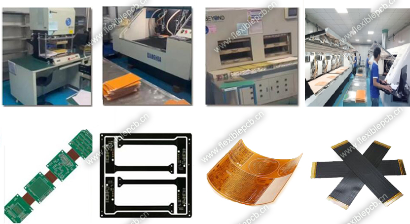
FPC Manufacturing
Flexible printed circuits (FPC) are made with a photolithographic technology. An alternative way of making flexible foil circuits or flexible flat cables (FFCs) is laminating very thin (0.07 mm) copper strips in between two layers of PET. These PET layers, typically 0.05 mm thick, are coated with an adhesive which is thermosetting, and will be activated during the lamination process. FPCs and FFCs have several advantages in many applications:
Tightly assembled electronic packages, where electrical connections are required in 3 axes, such as cameras (static application).
Electrical connections where the assembly is required to flex during its normal use, such as folding cell phones (dynamic application).
Electrical connections between sub-assemblies to replace wire harnesses, which are heavier and bulkier, such as in cars, rockets and satellites.
Electrical connections where board thickness or space constraints are driving factors.
Single-sided flex PCB circuits
Single-sided flexible circuits have a single conductor layer made of either a metal or conductive (metal filled) polymer on a flexible dielectric film. Component termination features are accessible only from one side. Holes may be formed in the base film to allow component leads to pass through for interconnection, normally by soldering. Single sided flex circuits can be fabricated with or without such protective coatings as cover layers or cover coats, however the use of a protective coating over circuits is the most common practice. The development of surface mounted devices on sputtered conductive films has enabled the production of transparent LED Films, which is used in LED Glass but also in flexible automotive lighting composites
Double-sided flex pcb circuits
Double-sided flex circuits are flex circuits having two conductor layers. These flex circuits can be fabricated with or without plated through holes, though the plated through hole variation is much more common. When constructed without plated through holes and connection features are accessed from one side only, the circuit is defined as a "Type V (5)" according to military specifications. It is not a common practice but it is an option. Because of the plated through hole, terminations for electronic components are provided for on both sides of the circuit, thus allowing components to be placed on either side. Depending on design requirements, double-sided flex circuits can be fabricated with protective coverlayers on one, both or neither side of the completed circuit but are most commonly produced with the protective layer on both sides. One major advantage of this type of substrate is that it allows crossover connections to be made very easy. Many single sided circuits are built on a double sided substrate just because they have one of two crossover connections. An example of this use is the circuit connecting a mousepad to the motherboard of a laptop. All connections on that circuit are located on only one side of the substrate, except a very small crossover connection which uses the second side of the substrate
Multilayer flex pcb circuits
Flex circuits having three or more layers of conductors are known as multilayer flex circuits. Commonly the layers are interconnected by means of plated through holes, though this is not a requirement of the definition for it is possible to provide openings to access lower circuit level features. The layers of the multilayer flex circuit may or may not be continuously laminated together throughout the construction with the obvious exception of the areas occupied by plated through-holes. The practice of discontinuous lamination is common in cases where maximum flexibility is required. This is accomplished by leaving unbonded the areas where flexing or bending is to occur.
Rigid-flex pcb circuits
Rigid-flex circuits are a hybrid construction flex circuit consisting of rigid and flexible substrates which are laminated together into a single structure. Rigid-flex circuits should not be confused with rigidized flex constructions, which are simply flex circuits to which a stiffener is attached to support the weight of the electronic components locally. A rigidized or stiffened flex circuit can have one or more conductor layers. Thus while the two terms may sound similar, they represent products that are quite different.
The layers of a rigid flex are also normally electrically interconnected by means of plated through holes. Over the years, rigid-flex circuits have enjoyed tremendous popularity among military product designer, however the technology has found increased use in commercial products. While often considered a specialty product for low volume applications because of the challenges, an impressive effort to use the technology was made by Compaq computer in the production of boards for a laptop computer in the 1990s. While the computer's main rigid-flex PCBA did not flex during use, subsequent designs by Compaq utilized rigid-flex circuits for the hinged display cable, passing 10s of 1000s of flexures during testing. By 2013, the use of rigid-flex circuits in consumer laptop computers is now common.
Rigid-flex boards are normally multilayer structures; however, two metal layer constructions are sometimes used.


Categories
Latest News
Contact Us
Contact: Ms Tracy
Phone: 0086 18682010757
Tel: 0086 18682010757
Add: Building9,Xinyuan Industrial Park,Tangwei,Fuyong,Baoan,Shenzhen,China
 Tracy
Tracy