Printed Circuit Boards
4 Layer Flex Printed Circuit Board Manufacturers From China
- flex pcb manufacturer
- rigid flex pcb
- quick turn flex pcb
- flex circuit
- Product description: flex pcb flex pcb manufacturer rigid flex pcb flex circuit rigid flex quick turn flex pcb flexible printed circuit flexible circuit board jlcpcb flex pcb rigid flex pcb manufacturer flex pcb
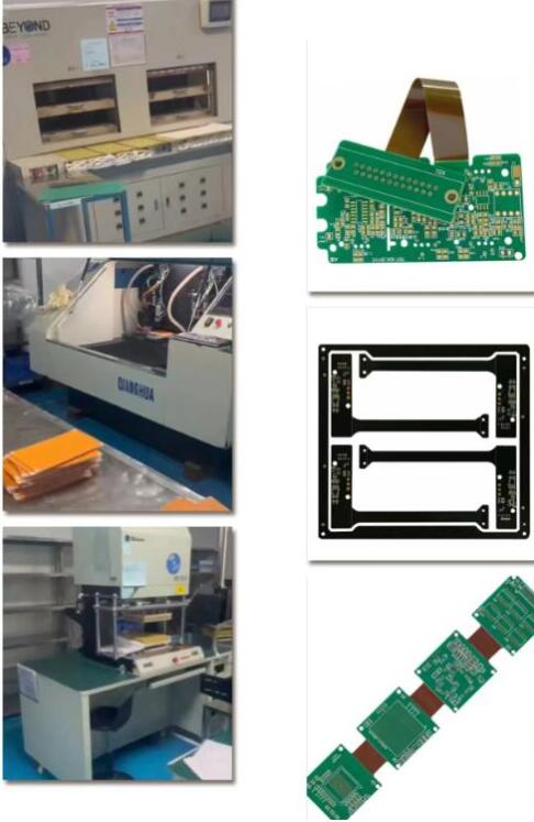
4 Layer Flex printed circuit board Manufacturers From China
Product Introduction
Application field: Security engineering
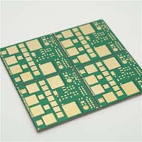
Material: Shengyi TG170-S1000
Number of floors: 4
Plate thickness: 2.0 ± 0.1mm
Minimum aperture: 0.15mm
Minimum line width/line spacing: 0.08mm
Copper thickness: 1OZ each on the inner and outer layers
Solder resistance: green oil with white letters
Surface technology: sinking gold
Product features: 0.1mm hole to line, 0.2mm BGA pad, resin plug required for holes in the pad
The manufacturing process of flex PCBs presents some unique challenges compared to rigid PCBs. Here are some common challenges encountered during the manufacturing of flex PCBs:
1. Material Handling: Flex PCB materials, such as polyimide or polyester, are delicate and flexible, requiring careful handling throughout the manufacturing process. Specialized equipment and procedures are needed to prevent damage or distortion during cutting, drilling, or lamination.
2. Dimensional Stability: Flex PCBs are highly flexible, and maintaining dimensional stability during manufacturing can be challenging. The materials used may expand or contract due to changes in temperature or humidity, which can affect the accuracy of circuit patterns and lead to misalignments during assembly.
3. Circuit Patterning: Etching or laser ablation processes used to create circuit patterns on flex PCBs can be more complex compared to rigid PCBs. The flexible substrate requires precise control of etching parameters to ensure proper circuit integrity without causing damage or undercutting of traces.
4. Plating and Drilling: Drilling holes in flex PCBs and plating them to establish electrical connections between layers can be challenging. The flexibility of the material can cause deformation or misalignment during drilling, leading to registration issues between layers or difficulty in achieving reliable plating quality.
5. Bending and Folding: Flex PCBs are designed to be bent or folded, but excessive stress or improper bending techniques can lead to cracks or breaks in the circuitry. It is crucial to ensure that the chosen bending radius and folding methods are suitable for the specific design and application requirements.
6. Component Assembly: Mounting electronic components on flex PCBs requires careful consideration. The flexibility of the board can affect the soldering process, and the design should accommodate the potential movement and stress that may occur during bending or flexing.
7. Testing and Inspection: Traditional testing methods used for rigid PCBs may not be directly applicable to flex PCBs. The flexibility and unique design characteristics of flex PCBs require specialized testing procedures to ensure electrical connectivity, signal integrity, and reliability.
To overcome these challenges, it is important to work closely with experienced flex PCB manufacturers or design engineers who are familiar with the intricacies of flex PCB manufacturing. They can provide guidance on material selection, design optimization, manufacturing techniques, and quality control measures to ensure successful production of flex PCBs.
Could you explain how the flexibility of flex PCBs affects the soldering process in component assembly?
Absolutely, the flexibility of flex PCBs can have a significant impact on the component assembly and soldering process. Here's a more detailed explanation:
1. Solder Joint Reliability:
- Flex PCBs are designed to bend and flex during their intended use. This flexibility can cause stress and strain on the solder joints between the components and the board.
- The repeated bending or flexing can lead to fatigue and eventual failure of the solder joints, compromising the electrical connections over time.
2. Component Placement:
- The placement of components on a flex PCB must consider the board's flexibility. Components should be positioned in a way that minimizes stress on the solder joints during bending or flexing.
- Placing components near the neutral axis of the flex PCB, where there is minimal flexing, can help reduce the stress on the solder joints.
3. Soldering Techniques:
- Conventional soldering methods used for rigid PCBs may not be directly applicable to flex PCBs. The flexibility of the board can affect the heat transfer during soldering, leading to potential issues like solder balling or incomplete wetting.
- Specialized soldering techniques, such as reflow soldering or wave soldering, may be required to ensure reliable solder joints on flex PCBs.
4. Solder Paste Considerations:
- The choice of solder paste used for component assembly on flex PCBs is crucial. The solder paste must be formulated to withstand the flexibility of the board without compromising its adhesion or mechanical properties.
- Solder pastes with higher metal content or specific additive formulations may be preferred to enhance the reliability of solder joints on flex PCBs.
5. Post-Soldering Inspection:
- Due to the flexible nature of the board, visual inspection of solder joints on flex PCBs can be more challenging compared to rigid PCBs.
- Advanced inspection techniques, such as X-ray imaging or automated optical inspection (AOI), may be required to thoroughly evaluate the quality and integrity of solder joints on flex PCBs.
To address these challenges, flex PCB manufacturers and assembly houses often employ specialized processes and equipment tailored for flex PCB assembly. This includes the use of dedicated solder paste, specialized pick-and-place machines, and controlled bending fixtures during the soldering process.
Collaboration with experienced flex PCB manufacturers or assembly service providers is crucial to ensure the successful and reliable assembly of components on flex PCBs.


Categories
Latest News
Contact Us
Contact: Ms Tracy
Phone: 0086 18682010757
Tel: 0086 18682010757
Add: Building9,Xinyuan Industrial Park,Tangwei,Fuyong,Baoan,Shenzhen,China
 Tracy
Tracy