Printed Circuit Boards
FPC Manufacture Flexible PCB Assembly Supplier PCBA Distributor Circuit Board custom PCB Manufacturing
- flex pcb manufacturer
- rigid flex pcb
- flex pcb prototype
- semi flex pcb
- Product description: fast turn flex pcb quick turn flex circuits flex pcb prototyping jlcpcb flexible pcb flex pcb thickness custom flexible pcb flex circuit design flex pcb assembly flex pcb design guidelines ri
FPC Manufacture Flexible PCB Assembly Supplier PCBA Distributor Circuit Board custom PCB Manufacturing
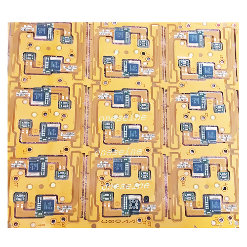
Product Introduction
Number of layers: 6
Plate thickness: 0.13mm
Minimum aperture: 0.2
Minimum line width/line spacing: 0.1mm
Copper thickness: 1OZ
Solder resistance: yellow film with white letters
Surface technology: ENIG
Sample time: 3-5 days
Batch time: 15 working days
Advantage of FPCs
Potential to replace multiple rigid boards and/or connectors
Single-Sided circuits are ideal for dynamic or high-flex applications
Stacked FPCs in various configurations
Disadvantages of FPCs
Cost increase over rigid PCBs
Increased risk of damage during handling or use
More difficult assembly process
Repair and rework is difficult or impossible
Generally worse panel utilization resulting in increased cost
Frequently Asked Questions and Answers
QA 1: How long does it take to proof a single-sided flexible circuit board?
It only takes 1-3 days for flexible boards and general-purpose circuit boards. Simple single-sided and double-sided layout soft board, proofing cycle 1-3 days.
QA 2: Does ONESEINE FPC provide free circuit board samples?
Yes, if the MOQ is more than 500pcs, we can provide free samples, and at the same time will print 10pcs more for regular delivery.
QA 3: How many layers of flexible circuit boards can you sample?
There is no big difference in the production process between PCB design and proofing. ONESEINE FPC can produce circuit boards with 1-10 layers. At the same time, it has its own SMT factory to complete the process of patch assembly, and solve the customer's circuit board needs in one stop.
QA 4: How long does it take for the Flexible PCB sample of ONESEINE FPC to be finished??
In addition to the number of layers of the PCB, the wiring density, application difficulty and material grade of the circuit board will directly affect the entire cycle of circuit board proofing. We go all out and can send flex board samples within 48-72 hours.
QA 5: Is the flex circuit board proofing done by your company independently?
Yes, as the original factory in Shenzhen, China, we can complete FPC design, prototyping and mass production services in one stop.
QA 6: How to calculate the cost of flexible circuit board proofing?
The circuit board sample fee depends on the number of layers, copper thickness, size, surface treatment and other parameters.
Flexible PCB concept:
Flexible printed circuit board , also known as "FPC soft board" is made of flexible insulating substrate printed circuit, with a lot of advantage that rigid printed circuit board does not have .
For example, it can be free to bend, winding, folding, can be arranged in accordance with the requirements of any spatial arrangement, and in any three-dimensional space to move and stretch, so as to achieve the integration of component assembly and wire connections. The use of FPC can greatly reduce the volume of electronic products, and suit for high-density, small, highly reliable needs. Therefore, FPC in the aerospace, military, mobile communications, notebook computers, computer peripherals, PDA, digital cameras and other fields or products have been widely used.
Flexible electronics, also known as flex circuits, is a technology for assembling electronic circuits by mounting electronic devices on flexible plastic substrates, such as polyimide, PEEK or transparent conductive polyester film. Additionally, flex circuits can be screen printed silver circuits on polyester. Flexible electronic assemblies may be manufactured using identical components used for rigid printed circuit boards, allowing the board to conform to a desired shape, or to flex during its use. An alternative approach to flexible electronics suggests various etching techniques to thin down the traditional silicon substrate to few tens of micrometers to gain reasonable flexibility (~ 5 mm bending radius)
FPC Manufacturing
Flexible printed circuits (FPC) are made with a photolithographic technology. An alternative way of making flexible foil circuits or flexible flat cables (FFCs) is laminating very thin (0.07 mm) copper strips in between two layers of PET. These PET layers, typically 0.05 mm thick, are coated with an adhesive which is thermosetting, and will be activated during the lamination process. FPCs and FFCs have several advantages in many applications:
Tightly assembled electronic packages, where electrical connections are required in 3 axes, such as cameras (static application).
Electrical connections where the assembly is required to flex during its normal use, such as folding cell phones (dynamic application).
Electrical connections between sub-assemblies to replace wire harnesses, which are heavier and bulkier, such as in cars, rockets and satellites.
Electrical connections where board thickness or space constraints are driving factors.
When selecting the flexible substrate material for a flex circuit prototype, there are several key considerations to keep in mind:
oneseine
1. Flexibility and Bend Radius:
- The substrate material should be able to withstand the required bending and flexing without cracking or breaking.
- Consider the minimum bend radius needed for your application and choose a material that can accommodate it.
- Common flexible substrate materials include polyimide, polyester (PET), and polyethylene terephthalate (PET).
2. Thermal Properties:
- Understand the operating temperature range for your application and select a substrate material with appropriate thermal stability.
- The coefficient of thermal expansion (CTE) of the substrate should be compatible with the materials used for traces, components, and other layers.
- Polyimide generally has better thermal performance than polyester or PET.
3. Electrical Properties:
- The dielectric constant and dissipation factor of the substrate material can affect the electrical performance of the flex circuit.
- Choose a material with low dielectric constant and dissipation factor to minimize signal integrity issues.
- Polyimide generally has better electrical properties than polyester or PET.
4. Chemical Resistance:
- Consider the exposure to chemicals, solvents, or other environmental factors the flex circuit may encounter.
- Select a substrate material that is resistant to the expected chemicals and can withstand the fabrication processes (e.g., etching, plating).
- Polyimide typically has better chemical resistance than polyester or PET.
5. Availability and Cost:
- Evaluate the availability and cost of the flexible substrate materials, as they can vary depending on the supplier and order quantities.
- For prototyping, it may be more cost-effective to use standard off-the-shelf materials, while custom materials may be considered for production.
6. Thickness and Stiffness:
- The thickness of the substrate can affect the overall flexibility and stiffness of the flex circuit.
- Thinner substrates generally offer more flexibility, but they may be more prone to handling challenges and potential damage.
- Consider the thickness that best suits your application's requirements.
Polyimide is a widely used flexible substrate material for flex circuit prototyping and manufacturing, and it offers several key advantages:
oneseine
1. Superior Flexibility and Durability:
- Polyimide has excellent flexibility, allowing it to withstand repeated bending and flexing without cracking or breaking.
- It has a high resistance to fatigue, making polyimide-based flex circuits suitable for applications with dynamic flexing requirements.
2. Thermal Stability:
- Polyimide has a high glass transition temperature (Tg) and can operate at elevated temperatures, typically up to 260°C.
- This thermal stability makes polyimide suitable for applications with high-temperature environments or processes, such as soldering.
3. Excellent Electrical Properties:
- Polyimide has a low dielectric constant and dissipation factor, which helps maintain signal integrity and minimizes crosstalk in high-frequency applications.
- It also exhibits high insulation resistance and dielectric strength, enabling the use of fine-pitch traces and high-density circuits.
4. Chemical and Environmental Resistance:
- Polyimide is highly resistant to a wide range of chemicals, solvents, and environmental factors, such as moisture and UV exposure.
- This resistance makes polyimide-based flex circuits suitable for applications in harsh environments or where they may be exposed to various chemicals.
5. Dimensional Stability:
- Polyimide has a low coefficient of thermal expansion (CTE), which helps maintain dimensional stability and minimize distortion during fabrication and assembly.
- This property is particularly important for achieving high-precision, high-density circuits.
6. Availability and Customization:
- Polyimide-based flex circuit materials are widely available from various suppliers, making them accessible for prototyping and production.
- These materials can also be customized in terms of thickness, copper foil weight, and other specifications to meet specific design requirements.
While polyimide offers many advantages as a flexible substrate material, there are a few limitations and drawbacks to consider when using it for flex circuit prototyping:
oneseine
1. Higher Cost:
- Polyimide-based flex circuit materials are generally more expensive compared to other flexible substrate options, such as polyester (PET) or polyethylene terephthalate (PET).
- This higher cost can be a factor, especially for prototyping or low-volume production.
2. Moisture Absorption:
- Polyimide has a higher moisture absorption rate compared to some other flexible substrates.
- This moisture absorption can affect the electrical properties and dimensional stability of the flex circuit, particularly in high-humidity environments.
- Special handling and storage conditions may be required to mitigate this issue.
3. Difficulty in Cutting and Shaping:
- Polyimide is a relatively stiff and durable material, which can make it more challenging to cut and shape the flex circuit using standard cutting tools.
- This may require specialized equipment, such as laser cutters or precision die-cutting tools, to achieve clean and accurate cuts.
4. Adhesion Challenges:
- Bonding polyimide to other materials, such as adhesives or encapsulation layers, can sometimes be more challenging compared to other flexible substrates.
- Careful selection of compatible adhesives and surface preparation techniques may be necessary to ensure strong and reliable adhesion.
5. Potential for Delamination:
- In some cases, the copper traces or other layers on a polyimide-based flex circuit may be more prone to delamination, especially if the circuit is subjected to high levels of flexing or thermal cycling.
- Proper design, fabrication, and assembly techniques are crucial to mitigate the risk of delamination.
6. Limited Availability of Prepreg Materials:
- Polyimide-based prepreg materials, which are used for multi-layer flex circuit construction, may have more limited availability compared to other substrate options.
- This can make it more challenging to prototype or fabricate complex, multi-layer flex circuits with polyimide.


Categories
Latest News
Contact Us
Contact: Ms Tracy
Phone: 0086 18682010757
Tel: 0086 18682010757
Add: Building9,Xinyuan Industrial Park,Tangwei,Fuyong,Baoan,Shenzhen,China
 Tracy
Tracy